Network Path Reporting and Rendering
Network path is a reconstruction of routes in a network taken by the traffic between a pair of communicating peers A and B (VM-to-VM, VM-to-Host, and Host-to-Host). Paths from A to B and from B to A are reported separately. It is important to keep in mind that flow-based path resolution is a best effort process, as device adjacency may not be certain. Path reporting relies on forwarding information (next hop), when available, and on traffic statistical methods of the Module. In certain cases additional path resolution could be achieved by superimposing paths from A to B and from B to A. However, some segments of the network routes may remain unresolved, and are shown with dashed lines. Let’s consider the following scenarios.
Scenario 1. Partially resolved network path

This example shows a partially resolved network path in the VM1 -> VM2 direction. Please note that the first hop (Host1 -> ToR1) is not resolved: ToR1 is a first network node in the segment which reports VM1 -> VM2 communication but we have no knowledge if there are other network nodes between Host1 and ToR1 which may be forwarding the traffic and not configured to send flows to NFO.
Scenario 2. Fully resolved network path

A complete resolved network path is produced by superimposing VM1 to VM2 and VM2 to VM1 communications observations, as each direction complements the unresolved segment of the path in the opposite direction.
Scenario 3. Multiple intersecting segments
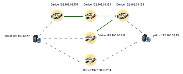
This example shows topology with five devices where network traffic from Host1 (192.168.66.12) to Host2 (192.168.63.15) may pass in three different ways: D1 (192.168.63.151) to D3 (192.168.63.153) to D5 (192.168.63.155), D4 (192.168.63.252) to D5 (192.168.63.155), and D2 (192.168.63.254). In practice this is a common load balancing scenario.
Please note a dashed line between D5 and Host2. This means that none of the nodes in this path was determined to be adjacent to the Host2 and therefore this segment is shown as unresolved. A dashed line between D2 and Host2 implies that traffic flowing from Host1 to Host2 was reported by device D2 which did not provide any forwarding information and was not reported as next hop by any of the other devices, so both segments Host1 to D2 and D2 to Host2 are shown as unresolved.
Scenario 4. “A bag of routers”
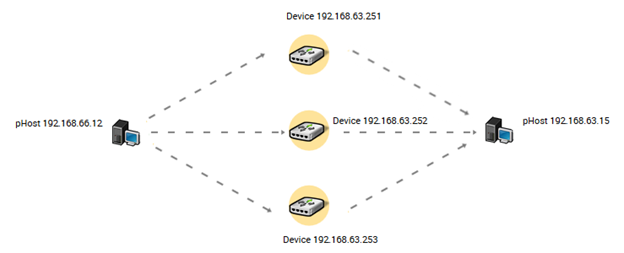
In this example all network devices between Host1 (192.168.66.12) and Host2 (192.168.63.15) did not report any forwarding information, therefore all segments of three paths are shown as unresolved.
Scenario 5. Multiple paths to a device

In this example device D1 reports traffic from Host1 (192.168.66.12) to Host2 (192.168.63.15) via a plurality of the interfaces. Such situation is possible when there is one or more intermediate network devices situated between Host1 and D1 (192.168.63.252) which do not report the traffic flows.